

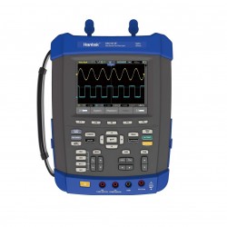


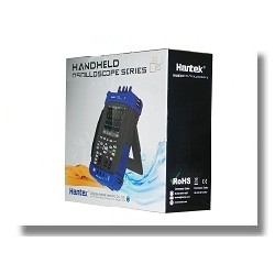
Oscilloscopio portatile per auto con cinque funzioni in una:
Oscilloscopio / Registratore / DMM / Analizzatore di spettro FFT / Contatore di frequenza.
2 canali / 70 MHZ.
Include KIT DIAGNOSTIVO AUTOMOTIVE.
Ampio schermo LCD TFT a colori ad alta risoluzione da 5,6 pollici (640 * 480).
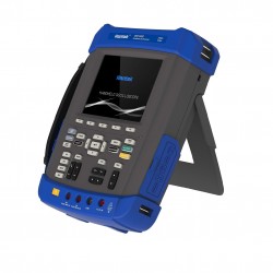
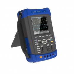
Classificazione IP-51 per polvere, umidità e vibrazioni per resistere ad ambienti difficili.
Indicatore di batteria con connettore che consente una facile sostituzione.
Alloggiamento batteria standard 18650.
Foro di blocco antifurto, treppiede con foro fisso, corda sospesa, luce FLASH che consente l'uso in ambienti bui.
Frequenza di campionamento 1GSa / s, profondità di memoria 2M, 6000 conteggi DMM.
The Kit include:
Portable oscilloscope 2 channels and 70 Mhz
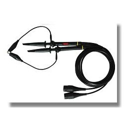
Inductive probe 10000: 1 for high voltage (Secondary)
Attenuator 20: 1
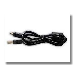
Extension cable BNC to Banana
Set of large crocodile clips with banana plug
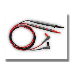
Acupuncture set with banana plugs
Oscilloscope probe with attenuation 1/10
CD with drivers, software and documentation
| Model | DSO1072E | DSO1102E | DSO1152E | DSO1202E |
| Bandwidth | 70MHZ | 100MHZ | 150MHZ | 200MHZ |
| Acquisition | ||||
| Sample Modes | Real-Time Sample | |||
| Acquisition Modes | ||||
| Normal | Normal data only | |||
| Peak Detect | High-frequency and randon glith capture | |||
| Average | Wavefom Average, selectable 4,8,16,32,64,128 | |||
| Inputs | ||||
| Inputs Coupling | AC, DC, GND | |||
| Inputs Impendance | 1MΩ±2% ‖ 20pF±3pF | |||
| Probe Attenuation | 1X, 10X | |||
| Supported Probe Attenuation Factor | 1X, 10X, 100X, 1000X | |||
| Maximum Input Voltage | CAT I and CAT II: 300VRMS (10×), Installation Category; CAT III: 150VRMS (1×) |
|||
| Horizontal System | ||||
| Sample Rate Range | 1GS/s | |||
| Waveform Interpolation | (sin x)/x | |||
| Record Length | 2M | |||
| SEC/DIV Range | 4ns/div~2000s/div, in a 2, 4, 8 sequence | 2ns/div~2000s/div, in a 2, 4, 8 sequence | ||
| Sample Rate and Delay Time Accuracy |
±50ppm over any ≥ 1ms time interval | |||
| Scanning Speed Range | 4ns/div to 8ns/div; (-8div x s/div) to 40ms; 20ns/div to 80μs/div;(-8div×s/div) to 40ms 200μs/div to 40s/div; (-8div×s/div) to 400s |
2ns/div to10ns/div; (-4div×s/div) to 20ms; |
||
| Delta Time Measurement Accuracy (Full Bandwidth) |
Single-shot, Normal mode:± (1 sample interval +100ppm × reading + 0.6ns); >16 averages:± (1 sample interval + 100ppm × reading + 0.4ns); Sample interval = s/div ÷ 200 |
|||
| Vertical System | ||||
| Vertical Resolution | 8-bit resolution, all channel sampled simultaneously | |||
| Volts Range | 2mV/div to 100V/div at input BNC | |||
| Bandwidth | 70MHz | 100MHz | 150MHz | 200MHz |
| Rise Time at BNC( typical) | 5ns | 3.5ns | 2.3ns | 1.8ns |
| Analog Bandwidth in Normal and Average modes at BNC or with probe, DC Coupled |
±400V(100V/div-20V/div); ±50V(10V/div-5V/div) ±40V(2V/div-500mV/div); ±2V(200mV/div-50mV/div) ±400mV(20mV/div-2mV/div) |
|||
| Math | +, -, *, /, FFT | |||
| FFT | Windows:Hanning, Flatop, Rectamgular, Bartlett, Blackman; 1024 sample point | |||
| Bandwidth Limit | 20MHz | |||
| Low Frequency Response (-3db) | ≤10Hz at BNC | |||
| DC Gain Accuracy | ±3% for Normal or Average acquisition mode, 100V/div to 10mV/div. ±4% for Normal or Average acquisition mode, 5mV/div to 2mV/div. |
|||
| DC Measurement Accuracy, Average Acquisition Mode |
Measurement Type: Average of ≥ 16 waveforms with vertical position at zero Accuracy: ± (3% × reading + 0.1div + 1mV) when 10mV/div or greater is selected. Measurement Type: Average of ≥ 16 waveforms with vertical position not at zero Accuracy: ± [3% × (reading + vertical position) + 1% of vertical position + 0.2div]. |
|||
| Volts Measurement Repeatability, Average Acquisition Mode |
Delta volts between any two averages of ≥16 waveforms acquired under same setup and ambient conditions | |||
| Trigger System | ||||
| Trigger Types | Edge, Video, Pulse, Slope, Over time, Alternative | |||
| Trigger Source | CH1, CH2, AC Line | |||
| Trigger Modes | Auto, Normal, Single | |||
| Coupling Type | DC, AC, HF Reject, LF Reject, Noise Reject | |||
| Trigger Sensitivity (Edge Trigger Type) |
DC(CH1,CH2): 1div from DC to 10MHz; 1.5div from 10MHz to 100MHz; 2div from 100MHz to Full; AC: Attenuates signals below 10Hz ; HF Reject: Attenuates signals above 80kHz; LF Reject: Same as the DC-coupled limits for frequencies above 150kHz; attenuates signals below 150kHz. |
|||
| Trigger Level Range | CH1/CH2: ±8 divisions from center of screen; | |||
| Trigger Level Accuracy( typical)Accuracy is for signals having rise and fall times ≥20ns | CH1/CH2: 0.2div × volts/div within ±4 divisions from center of screen; | |||
| Set Level to 50%(typical) | Operates with input signals ≥50Hz | |||
| Video Trigger | ||||
| Video Trigger Type | CH1, CH2: Peak-to-peak amplitude of 2 divisions; | |||
| Signal Formats and Field Rates | Supports NTSC, PAL and SECAM broadcast systems for any field or any line | |||
| Holdoff Range | 100ns ~ 10s | |||
| Pulse Width Trigger | ||||
| Pulse Width Trigger Mode | Trigger when (< , >, = , or ≠); Positive pulse or Negative pulse | |||
| Pulse Width Trigger Point | Equal: The oscilloscope triggers when the trailing edge of the pulse crosses the trigger level. Not Equal: If the pulse is narrower than the specified width, the trigger point is the trailing edge. Otherwise, the oscilloscope triggers when a pulse continues longer than the time specified as the Pulse Width. Less than: The trigger point is the trailing edge. Greater than (also called overtime trigger): The oscilloscope triggers when a pulse continues longer than the time specified as the Pulse Width |
|||
| Pulse Width Range | 20ns ~ 10s | |||
| Slope Trigger | ||||
| Slope Trigger Mode | Trigger when (< , > , = , or ≠ ); Positive slope or Negative slope | |||
| Slope Trigger Point | Equal: The oscilloscope triggers when the waveform slope is equal to the set slope. Not Equal: The oscilloscope triggers when the waveform slope is not equal to the set slope. Less than: The oscilloscope triggers when the waveform slope is less than the set slope. Greater than: The oscilloscope triggers when the waveform slope is greater than the set slope. |
|||
| Time Range | 20ns ~ 10s | |||
| Overtime Trigger | ||||
| Over Time Modee | Rising edge or Falling edge | |||
| Time Range | 20ns ~ 10s | |||
| Alternative Trigger | ||||
| Trigger on CH1 | Internal Trigger: Edge, Pulse Width, Video, Slope | |||
| Trigger on CH2 | Internal Trigger: Edge, Pulse Width, Video, Slope | |||
| Trigger Frequency Counter | ||||
| Readout Resolution | 6 digits | |||
| Accuracy (typical) | ±30ppm (including all frequency reference errors and ±1 count errors) | |||
| Frequency Range | AC coupled, from 4Hz minimum to rated bandwidth | |||
| Signal Source | Pulse Width or Edge Trigger modes: all available trigger sources The Frequency Counter measures trigger source at all times, including when the oscilloscope acquisition pauses due to changes in the run status, or acquisition of a single shot event has completed. Pulse Width Trigger mode: The oscilloscope counts pulses of significant magnitude inside the 1s measurement window that qualify as triggerable events, such as narrow pulses in a PWM pulse train if set to < mode and the width is set to a relatively small time. Edge Trigger mode: The oscilloscope counts all edges of sufficient magnitude and correct polarity. Video Trigger mode: The Frequency Counter does not work. |
|||
| Measure | ||||
| Cursor Measurement | Manual: Voltage difference between cursors: △ V Time difference between cursors: △ T Reciprocal of △ T in Hertz (1/ΔT); Tracing: The valtage and time at a waveform point; |
|||
| Auto Measuerment | Frequency, Period, Mean, Pk-Pk, Cycli RMS, Minimum, Maximum, Rise time, Fall Time, +Pulse Width, -Pulse Width, Delay1-2Rise, Delay1-2Fall, +Duty, -Duty, Vbase, Vtop, Vmid, Vamp, Overshoot, Preshoot, Preiod Mean, Preiod RMS, | |||
| Scope Trendplot | 1.2M Point | |||
| General Specifications | ||||
| Display Resolution | 640 horizontal by 480 vertical pixels | |||
| Display Contrast | Adjustable (16 gears) with the progress bar | |||
| Probe Compensator Output | ||||
| Output Voltage( typical) | About 2Vpp into ≥ 1MΩ load | |||
| Frequency(typical) | 1kHz | |||
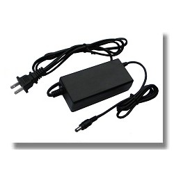
| Power Supply | ||||
| Supply Voltage | AC Input:100-240VACRMS,1.5A MAX,50Hz~60Hz; DC Output: 12V,3A | |||
| Power Consumption | <30W | |||
| Environmental | ||||
| Temperature | Operating: 32 ℉ to 122 ℉ (0 ℃ to 50 ℃ ); Nonoperating: -40 ℉ to 159.8 ℉ (-40 ℃ to +71 ℃ ) |
|||
| Cooling Method | Convection | |||
| Humidity | +104 ℉ or below (+40 ℃ or below): ≤90% relative humidity; 106 ℉ to 122 ℉ (+41 ℃ to 50 ℃ ): ≤60% relative humidity |
|||
| Altitude | Operating: Below 3,000m (10,000 feet); Nonoperaring: Below 15,000m(50,000 feet) |
|||
| Mechanical | ||||
| Size | 260mmmm; 220mm; 75mm | |||
| Weight | 2.5KG(without Packing) | |||
| DMM Mode | |||
| Max. Resolution | 6000 Counts | ||
| DMM Testing Modes | Voltage, Current, Resistance, Capacitance, Diode & Continuity | ||
| Max. Input Voltage | AC:600V, DC: 800V | ||
| Max. Input Current | AC: 10A, DC:10A | ||
| Input Impedance | 10MΩ | ||
| DMM TrendPlot | 1.2M Point | ||
| Range | Resolution | Accuracy | Resolution |
| DC Voltage | 60.00mV | ±1%±3 digit | 10uV |
| 600.0mV | 100uV | ||
| 6.000V | 1mV | ||
| 60.00V | 10mV | ||
| 600.0V | 100mV | ||
| 800V | 1V | ||
| AC Voltage | 60.00mV | ±1%±3 digit | 10uV |
| 600.0mV | 100uV | ||
| 6.000V | 1mV | ||
| 60.00V | 10mV | ||
| 600.0V | 100mV | ||
| DC Current | 60.00mA | ±1%±5 digit | 10uA |
| 600.0mA | ±1.5%±5 digit | 100uA | |
| 6.000A | 1mA | ||
| 10.00A | 10mA | ||
| AC Current | 60.00mA | ±1%±5 digit | 10uA |
| 600.0mA | ±1.5%±5 digit | 100uA | |
| 6.000A | 1mA | ||
| 10.00A | 10mA | ||
| Resistance | 600 Ω | ±1%±3 digit | 0.1Ω |
| 6.000K Ω | 1Ω | ||
| 60.00K Ω | 10Ω | ||
| 600.0K Ω | 1KΩ | ||
| 6.000M Ω | 10KΩ | ||
| 60.00M Ω | ±1%±5 digit | 100KΩ | |
| Capacitance | 40.00nF | ±2%±5 digit | 10pF |
| 400.0nF | 100pF | ||
| 4.000uF | 1nF | ||
| 40.00uF | 10nF | ||
| 400.0uF | 100nF | ||
| Attention: the smallest capacitance value that can be measured in 5nF | |||
| Diode | 0V~2.0V | ||
| ON-OFF test | <10Ω |
||